What explosion-proof means
In (hazardous) locations where gas, vapor, or powder posing explosion risks is present or is assumed to be present in the air—for example, oil refineries and chemical plants—the technical measures (explosion-proof construction) implemented to prevent explosions are collectively referred to as explosion proofing, and devices incorporating such measures are referred to as explosion-proof devices.
The conditions required to ignite an explosion
An ignition source, combustible material (e.g., combustible gas), and combustion-supporting gas (e.g., oxygen) are referred to as the three factors required for combustion and explosion. No explosion can occur if even one of these factors is missing.
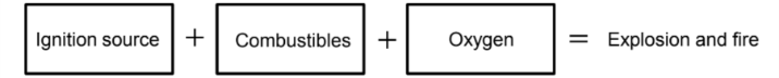
* Ignition source: fire, static electricity, impact, temperature, sparks, or electromagnetic radiation, etc.
* Combustible materials: dust (solid), vapor (liquid), gas, etc.
Hazardous locations and non-hazardous locations
Locations where an explosive atmosphere is present at levels requiring special preventive measures for the construction, installation, and use of electrical equipment or not present:
① Present (or potentially present)
⇒ Hazardous location (explosion-proof area)
② Not present
⇒ Non-hazardous location (non-explosion-proof area)
Types of explosion-proof construction
Riken Keiki gas detectors incorporate one of the following three explosion-proof design approaches.
Internal pressure explosion-proof construction “p”, oil ingress explosion-proof construction “o”, increased-safety explosion-proof construction “e”, resin-filled explosion-proof construction “m”, dust explosion-proof construction using container “t”, and special explosion-proof construction “s”
Explosion-proof certification in different countries
- International ⇒ IECEx
- European ⇒ ATEX
- North America ⇒ UL/cUL, FM/cFM * “c” corresponds to Canadian standard
- Brazil ⇒ INMETRO
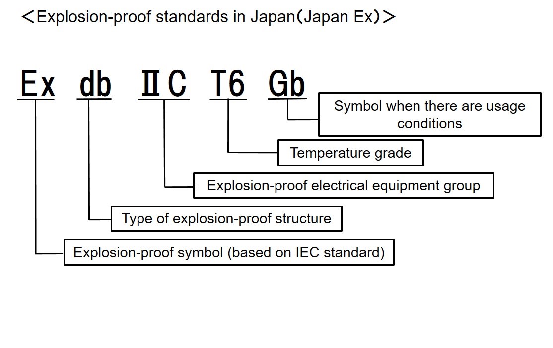
- Japan ⇒ Certificate of conformity for electrical equipment used in potentially explosive atmospheres (Japan Ex)
- China ⇒China Ex
- Taiwan ⇒ TS
- Republic of Korea ⇒ KCs
Classification of hazardous locations
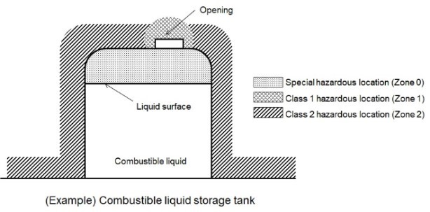
Special hazardous location (Zone 0)
Locations in which explosive atmospheres are present continuously or for extended periods
Example: ① Inside combustible gas containers or tanks
② Spaces above liquid surfaces in inflammable liquid containers or tanks
Type 1 hazardous location (Zone 1)
Locations in which explosive atmospheres are produced under normal conditions
Example: ① Locations where combustible gas or vapor may be emitted under normal operating conditions
② Locations where combustible gas or vapor is prone to leaking during maintenance or repairs
③ Indoor or poorly ventilated locations where combustible gas or vapor accumulates around openings
Type 2 hazardous location (Zone 2)
Locations free of explosive atmospheres or where explosive atmospheres are present under normal conditions only for short periods
Examples: ① Locations where combustible gas or vapor may leak if a container or plant is damaged by corrosion, deterioration, or damage
② Locations where combustible gas or vapor may be released in the event of an operating error or an abnormal reaction
③ Indoor locations surrounding or adjoining Type 1 hazardous locations associated with a remote possibility of combustible gas or vapor ingress
Explosion-proof construction types suitable for each type of hazardous location
| Hazardous area | Explosion-proof construction | Remarks |
|---|---|---|
| Special hazardous location (Zone 0) | Intrinsically safe explosion-proof construction (ia) | |
| Resin-filled explosion-proof construction (ma) | ||
| Type 1 hazardous location (Zone 1) | Flame-proof enclosure (d) | Explosion-proof construction items used in special hazardous locations (Zone 0) may also be used. |
| Internal-pressure explosion-proof construction (px, py)) | ||
| Increased safety explosion-proof construction (e) | ||
| Oil-filled explosion-proof construction (o) | ||
| Intrinsically safe explosion-proof construction (ib) | ||
| Resin-filled explosion-proof construction (mb) | ||
| Special explosion-proof construction (s) | ||
| Type 2 hazardous location (Zone 2) | Intrinsically safe explosion-proof construction (ic) | Explosion-proof construction items used in special hazardous locations (Zone 0) or Type 1 hazardous locations (Zone 1) may also be used. |
| Non-incendive explosion-proof construction (nA, nC, nR) | ||
| Resin-filled explosion-proof construction (mc) | ||
| Internal-pressure explosion-proof construction (pz) |
Explosion-proof class
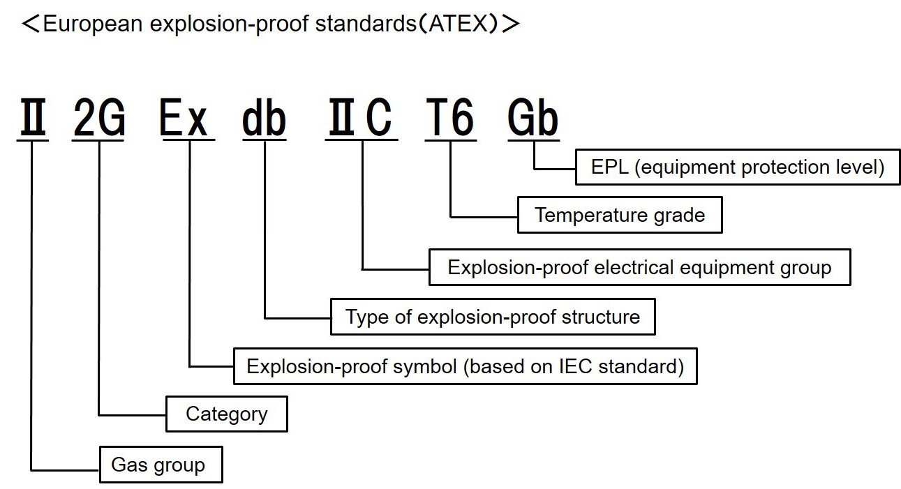
Gas groups
Gas groups are defined as Group I or Group II, depending on the usage environment. (See Table 1)
Group I
Electrical devices used in mines where explosive mine gas may be present
Group II
Electrical devices used in explosive gas atmospheres other than mines where explosive mine gas may be present
Category
These are categorized 1G to 3G depending on the presence of an explosive atmosphere. (See Table 1)
Table 1 Correlation between group and category
| Group | Category (94/4/EC) |
Zone | Presence of explosive atmosphere | |||
|---|---|---|---|---|---|---|
| Group Ⅰ (coal mines) |
M1 | Present (methane, dust) | ||||
| M2 | Potentially present (methane, dust) | |||||
| Group II | 1G | Zone 0 | Present continuously, frequently, or over extended periods | |||
| 2G | Zone 1 | Present intermittently during normal operation (potentially) | ||||
| 3G | Zone 2 | Present occasionally or only for short periods (Not present during normal operation) |
Explosion-proof symbol
Symbol indicating explosion-proof construction.
Explosion-proof construction type
Indicates the type of explosion-proof construction. (See Table 2)
Table 2 Type of explosion-proof construction
| Intrinsically safe explosion-proof construction | i (ia, ib) |
| Flame-proof enclosure | d (da, db) |
| Internal-pressure explosion-proof construction | p |
| Increased safety explosion-proof construction | e |
| Resin-filled explosion-proof construction | m |
| Non-incendive explosion-proof construction | n |
| Oil-filled explosion-proof construction | o |
| Special explosion-proof construction | s |
Explosion-proof electrical device groups
Depending on whether they feature flame-proof enclosures or intrinsically safe explosion-proof construction, respectively, explosion-proof electrical device groups (IIA, IIB, IIC) are classified as maximum safety gap or minimum ignition current. (See Table 3)
Table 3 Explosion-proof devices and explosion-proof class
| Explosion-proof class | Flame-proof enclosure | Intrinsically safe explosion-proof construction |
|---|---|---|
| Maximum safety gap range for gas or vapor | Minimum ignition current ratio range for gas or vapor | |
| II A | 0.9 mm or more | Over 0.8 |
| II B | Over 0.5 mm and less than 0.9 mm | 0.45 or higher and 0.8 or less |
| II C | 0.5 millimeters or less | Less than 0.45 |
* The minimum ignition current ratio is indicated with reference to the minimum ignition current for methane.
Maximum safety gap
This is the maximum joint gap that prevents the propagation of a flame to an external gas mixture through a 25 mm long joint in a flame-proof test container when the gas mixture with the highest flame propagation is ignited inside the specified test container.
Minimum ignition current
This is the minimum current for an inductive or resistive circuit used to ignite the most easily ignitable gas mixture in a spark ignition test.
Temperature grade
This is categorized based on the maximum surface temperature of the electrical device and the ignition temperature of the combustible gas or vapor. Combustible gases and vapor have their own specific ignition temperatures. The methods for measuring ignition temperature are internationally stipulated in IEC 60079-20-1 “Gas and vapour classification - Test methods and data”. Values measured by these measuring methods are often used. (See Table 4)Table 4 Temperature grade and ignition temperature
| Electrical device maximum surface temperature | Temperature class | Combustible gas vapor ignition temperature |
|---|---|---|
| 450 °C or less | T1 | Over 450 °C |
| 300 °C or less | T2 | Over 300 ℃ and 450 ℃ or less |
| 200 °C or less | T3 | Over 200 ℃ and 300 ℃ or less |
| 135 °C or less | T4 | Over 135 ℃ and 200 ℃ or less |
| 100 °C or less | T5 | Over 100 ℃ and 135 ℃ or less |
| 85 °C or less | T6 | Over 85 ℃ and 100 ℃ or less |
Ignition temperature
This refers to the minimum temperature of a heated surface leading to ignition when the heated surface is in contact with a mixture of combustible gas or vapor and air under specified conditions.
EPL (Equipment Protection Level)
Table 5 Explanation of EPL
| EPL | Protection | Zone for normal operation |
|---|---|---|
| Ga | “Extremely high protection” Protected by two independent explosion-proof functions or capable of maintaining explosion-proof performance even when two failures occur independently. ・ Equipment that becomes Ga by itself: Intrinsically safe explosion-proof construction “ia” ・ Two independent explosion-proof structures: Combining equipment with Gb structures |
Zone 0 |
| Gb | “High protection” Maintains explosion-proof performance even under normal operation, and maintains explosion-proof performance even in the presence of frequent severe disturbances to explosion-proof performance or in cases where faults may occur during normal use. ・ Flame-proof and intrinsically safe explosion-proof construction “ib”, flame-proof construction “d”, etc. |
Zone 1 |
| Gc | “Improved protection” Maintains explosion-proof performance only during normal operation. ・ Type n devices |
Zone 2 |
Gas detector groups and temperature grades for typical combustible gases and vapors
Gas detector groups and temperature grades for typical combustible gases and vapors
| Temperature class Group |
T1 | T2 | T3 | T4 | T5 | T6 |
| II A | Acetone Ammonia Isobutane Ethane Acetate Ethyl acetate Toluene Benzene Methane |
Isopentyl acetate Acetic anhydride Butane Propane Methanol |
Hexane | Acetaldehyde | ||
| II B | Carbon monoxide | Ethanol Ethylene Ethylene oxide |
||||
| II C | Hydrogen gas Hydrogen |
Acetylene | Carbon disulfide |
Reference:
Technical recommendations of the National Institute of Occupational Safety and Health JNIOSH-TR-No.44: 2012 (published by National Institute of Occupational Safety and Health, Japan)