Using gas detectors correctly
- Model selection and installation
This summarizes the information (e.g., type, features) needed to select a gas detector. Provides reference information to help you select the gas detectors best suited to your uses and requirements.

Selecting portable gas detectors

Riken Keiki offers a diverse product lineup to suit specific work environment gas characteristics and work details.
The correct selection and use of our gas detectors will ensure safety and peace of mind for users.

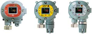
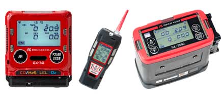
Portable gas detectors

These products are ideal for inspections before personnel enter tanks, manholes, or other locations that pose the risk of oxygen deficiency. They can also be worn on one’s person when handling hazardous gases.
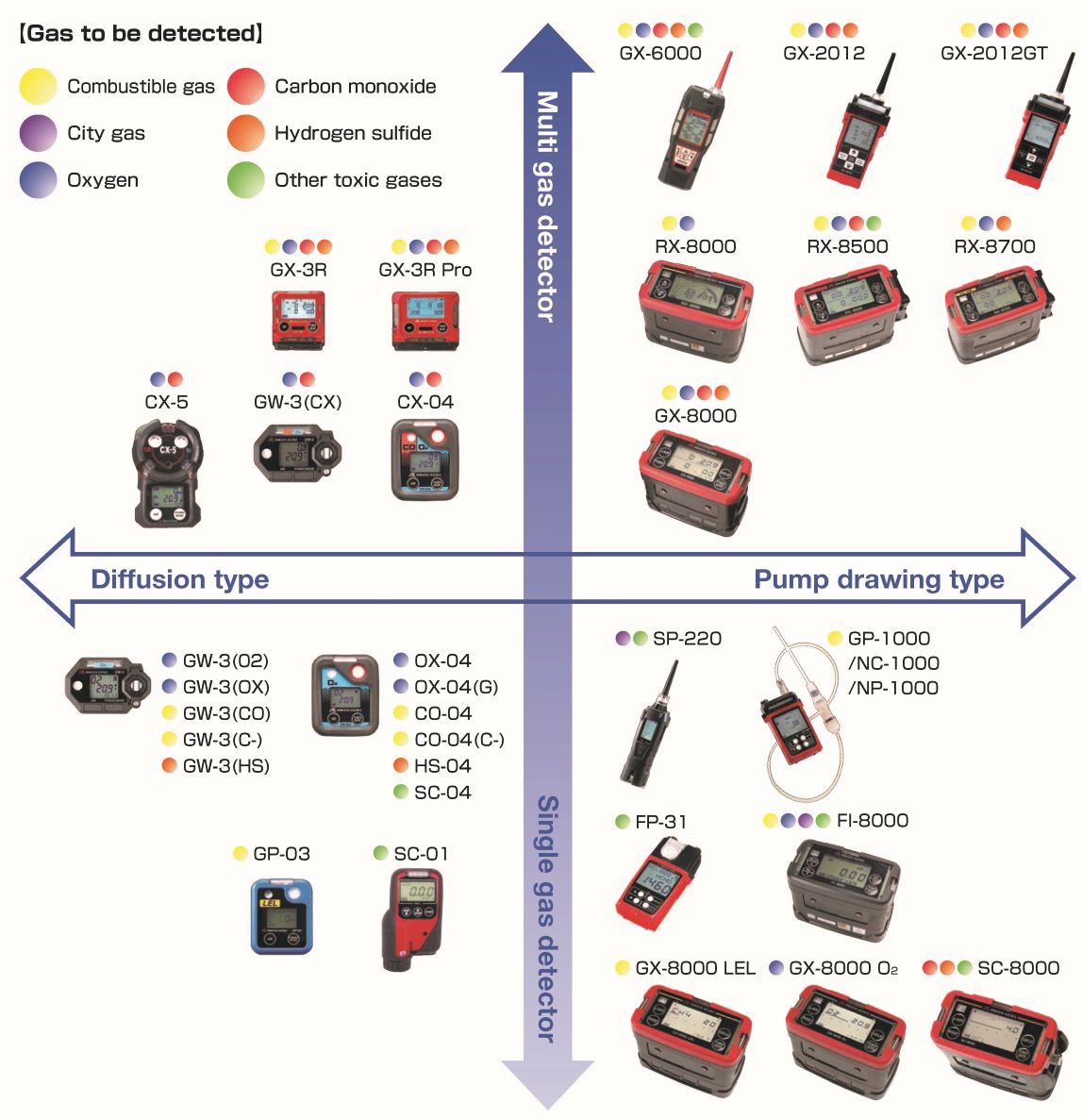
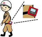
portable-1
Diffusion type

Diffusion type gas detectors detect gas leaks that come into contact with a sensor. They are worn on the person by workers to alert the user to hazards when gas is detected in the surroundings, allowing the user to move to a safe location.
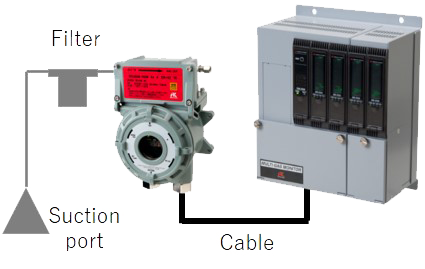
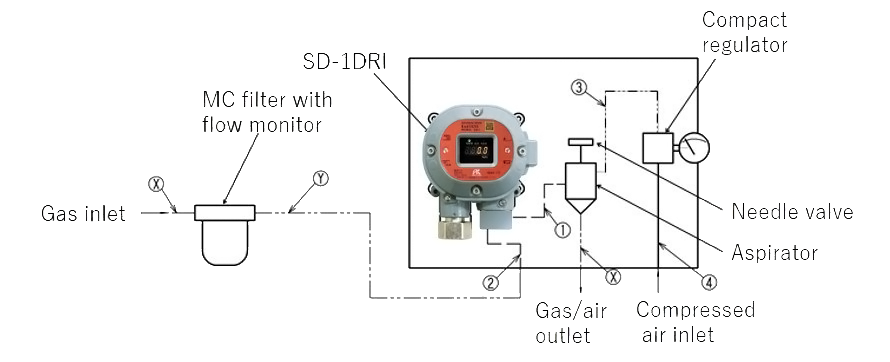
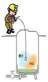
Diffusion type
Suction type

Suction type gas detectors have a built-in pump. Therefore, when working inside a tank or any other place where there is a risk of oxygen shortage, the hose connected to the gas detector can be placed inside the tank to detect the gas and confirm safety before work.

Suction type
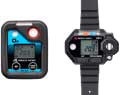
Single-gas detectors

These contain one type of gas sensor within a single detector. This makes them compact and lightweight, allowing them to be worn on a helmet or wristwatch-style.
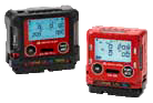
Single component
Multi-gas detectors

These contain multiple sensors within a single detector. They can detect multiple gases simultaneously, such as hazardous gases and oxygen. They can also display corresponding gas concentrations simultaneously.

Multi-gas
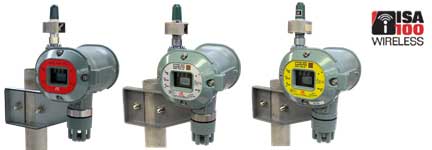
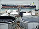
Explosion-proof products (explosion-proof areas)

Locations like petrochemical plants where combustible gases are generated require explosion-proof gas detectors to prevent the detectors themselves from becoming the source of ignition.

Single component
Hydrogen production facilities etc.
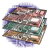
Non-explosion-proof products (non-explosion-proof areas)

Since there is no need for explosion-proof design, non-explosion-proof gas detectors are deployed in semiconductor plants and other locations where no combustible gases are generated.

Multi-gas
Semiconductor plants, etc.

Gas detectors must be selected to suit the particular application. Consider other factors, including the detection target gas, the purpose of detection (e.g., to prevent explosion, detect toxic gas leaks, concentration monitoring, leak checking), and certification with specific standards.

Types of portable gas detectors
Portable device chart

Selecting fixed gas detectors

Depending on the industry, plants and facilities can present many different potential gas-related hazards. Increased safety depends on correctly selecting and configuring systems to prevent hazards.
Riken Keiki offers a range of products to suit specific plants and work content.

Types of fixed gas monitoring systems

What are fixed gas monitoring systems?

These devices detect gases, display concentrations, and sound alarms. They are normally used in the form of a gas detector combined with an indicator/alarm unit.

What are fixed gas
detectors?

These gas detectors are designed to be installed in a specific location for continuous use and monitoring.
They detect gases using internal sensors.
They are generally used in conjunction with devices like indicator/alarm units and external buzzers.
Depending on the installation location, fixed gas detectors can be wall-mounted, panel-mounted, pole-mounted, or duct-insertion types.

What are transportable gas detectors?

These gas detectors are designed to be used fixed in a specific location, powered by an AC power supply. They are easily moved from place to place.
Gas is detected using internal sensors. These gas detectors can also be used in conjunction with devices like indicator/alarm units and external buzzers.

What are indicator/alarm units?

These devices are designed to receive signals from gas detectors and display gas concentrations and output alarms and contacts.
They can activate alarms using buzzers and lamps, and output contacts or 4 - 20 mA DC output.

System configuration

For large factories
Monitoring room, etc.
System PC
System

Signals from gas detectors in locations such as plants with a large number of detection points and detection target gases are centrally managed from a PC or PLC.
Plant area maps can be used to immediately identify where a gas leak has occurred.
Additional functions are available, such as trend graphs.

Trend graph function
System graph
Monitoring room, workplace, etc.
System PC
Indicator/alarm unit

The indicator and alarm unit receives signals from the gas detector and displays the gas concentration at the detection point. It also outputs alarm operation using a buzzer or lamp, alarm contact output, gas concentration analog signal and so on.

Workplace, duct, etc.
System PC
Gas detector heads

These actually detect gases using internal sensors.
These devices are used to transmit gas concentration signals to an indicator/alarm unit.

For small to medium sized factories
① Gas detector head only
Gas detector head only

A smart transmitter/gas detector including a concentration display, contacts, and 4 - 20 mA output can be used to control revolving lights and external buzzers using just a gas detector head.

② Installation example of gas detector head and indicator/alarm unit (Single-contact type)
Gas detector head only

Using a gas detector head in conjunction with an indicator/alarm unit allows the concentration to be read off at a remote safe location and at the location where the gas detector head is installed.

③ Installation example of gas detector head and indicator/alarm unit (Multi-contact type)
Gas detector head only

Using multiple gas detector heads in conjunction with a multi-contact indicator/alarm unit allows concentrations from multiple gas detectors installed at a site to be monitored from a single location.

Sampling method

Fixed gas monitors rely on the following three different sampling methods:

Diffusion type

Diffusion-type gas detectors are installed in locations where gas leaks and/or gas buildup are likely. They detect gas that reaches the detector via diffusion.

Sampling method 1
Suction type

Suction-type gas detectors use an internal or external pump to feed gas at a preset flow rate to the sensor. These are suitable for situations in which a gas leak location has been identified or if a gas detector cannot be installed directly at the detection point.

Sampling method 1
Aspirator suction type

Aspirator-type gas detectors use instrumentation air from an aspirator unit to feed gas at a preset flow rate. In contrast to pumps, these devices have no drive unit requiring a power supply and offer significant operating cost advantages.

Sampling method 1

Explosion-proof construction

In (hazardous) locations where gas, vapor, or powder posing explosion risks is present or is assumed to be present in the air—for example, oil refineries and chemical plants—the technical measures (explosion-proof construction) implemented to prevent explosions are collectively referred to as explosion proofing, and devices incorporating such measures are referred to as explosion-proof devices.

Types of explosion-proof construction
Intrinsically safe explosion-proof construction “i”

Design intended to eliminate the risk of arcing or sparks caused by electrical circuits igniting gas or vapor when the device is in a normal state or when it is in a specified failure state The electricity used is limited to prevent sparks or fires. The construction is classified as “ia” for up to two possible failures and “ib” for one possible failure (“ia” indicates a higher grade).

Flame-proof enclosure “d”

This refers to a design intended to withstand internal explosions without sustaining damage in the event of explosive atmospheres entering the device and to prevent the ignition of external gas or vapor.

Miscellaneous

Other types of construction include non-explosion-proof construction “n”, internal pressure explosion-proof construction “p”, oil ingress explosion-proof construction “o”, increased-safety explosion-proof construction “e”, resin-filled explosion-proof construction “m”, dust explosion-proof construction using container “t”, and special explosion-proof construction “s”.

Interpreting explosion-proof construction labeling
Example: Interpreting Japanese explosion-proof construction labeling

Ex

Explosion-proof symbol
(based on IEC standard)

db

Types of explosion-proof construction

ⅡC

Explosion-proof electrical device
group

T6

Temperature grade

GB

EPL
(equipment protection level)

Example: Interpreting European explosion-proof construction labeling

II

Gas group

2G

Category

Ex

Explosion-proof symbol
(based on IEC standard)

db

Types of explosion-proof construction

ⅡC

Explosion-proof electrical device
group

T6

Temperature grade

GB

EPL
(equipment protection level)

Gas sensor types

Main gas sensor types used in industrial gas detectors
Category Principles Detection method(overview) Detection gas
(main use)
Appearance
Electrochemical
sensor
Potentiostatic Electrolysis
Method,
Electrochemical type sensor
Detection by oxidation or reduction currents caused by electrolysis. Toxic gas
(TLV management)
Electrochemical sensor
Electrochemical
sensor
Membrane type Galvanic Cell Method Detection by the reduction reaction current caused by electrolysis. Oxygen
(Oxygen deficiency)
Electrochemical sensor
Optical sensor Interferometer Method,
Optical interferometer Method
Detection by the amount of movement of the interference fringes caused by the difference in the refractive indices of the gases. Combustible gas
(Explosion limit management)
Calorimetry
Optical sensor
Optical sensor Non-dispersive Infrared Method,
Non-dispersive infrared type Optical interferometer Method
It is detected by the change in the amount of absorption at a specific wavelength of infrared, which is unique to gas molecules. Combustible gas
(Explosion limit management)
Optical sensor
Solid sensor Semi-Conductor Method It is detected by the change in resistance value that occurs when the gas contacts the element surface. Toxic gas
(TLV management)
Combustible gas
(Low concentration management)
Solid sensor
Solid sensor New Ceramic Catalytic Method,
New Ceramic Catalytic Method Catalytic combustion Method
It is detected by the change in resistance value that occurs when gas comes into contact with the element surface and burns. Combustible gas
(Explosion limit management)
Solid sensor

* Riken Keiki is currently pursuing research and development on gas sensors using a wide range of sensing
   principles beyond those listed in the table above.
   Gas is detected using the optimum sensing principle to suit the installation location.

Click here for more information.

Interference gas effects

What are the effects of interference gases?

Because gas sensors use physical and chemical properties to detect, they may react (have sensitivity) to gases with similar properties to those of the gas to be detected.
For example, as shown in the diagram below, a contact combustion sensor (which uses the heat generated when combustible gas burns) is sensitive to all combustible gases, although there may be small or large differences depending on the gas type.

Effects of interference gas

Before selecting a gas detector, make sure you know what kinds of gas are present in the environment being measured.

Relative sensitivity data

Riken Keiki provides the following two types of relative sensitivity as information indicating the extent of interference effects due to gases other than the detection target gas:

Interference gas effect list

Example: Electrochemical type sensor

Sensor model: ES-K233 Detection target gas: NF3
Interference gas effect list
Relative sensitivity curve

Example: Catalytic combustion type sensor

Sensor model: HW-6211 Detection target gas: NH3
Interference gas effect list

Pipe material type and selection

Metal pipes

The metal pipes mainly used by Riken Keiki are either copper or stainless steel. These are used when gas detectors are installed in outdoor explosive areas—for example, petrochemical plants or chemical plants.

Comparison of stainless steel and copper pipes
Material Gas adsorption Gas durability Processing Cost
Copper pipes High adsorption Less durable compared to stainless steel pipes Easy to process Cheap
Stainless steel pipes Low adsorption Outstanding corrosion resistance Expensive High
Recommended gases

Copper pipes: Hydrocarbons and hydrogen gas at room temperature

Stainless steel pipes: Solvent gas that is liquid at room temperature, corrosive gases containing chlorine (Cl) and sulfur (S), and acetylene*
* Acetylene cannot be used with copper pipes because it reacts with copper to produce explosive copper acetylide.

Resin pipes

The resin pipes mainly used by Riken Keiki are Teflon (PTFE) pipes. While these generally have lower heat and pressure resistance compared to metal pipes, they have the advantage of being lightweight, flexible, and easy to process. They offer outstanding chemical resistance against organic solvents such as solvent vapor and alcohol. These are used when gas detectors are installed in indoor non-explosive areas such as at semiconductor and food processing plants.

Pipe delay time

Gas detectors are required to provide fast response times due to their role as safety protection devices. While the response time of the gas detector itself matters, rapid detection of gas leaks also requires taking into account the pipe length and pipe delay times.

Pipe delay time calculation method

Pipe internal volume = Internal diameter / 2 × Internal diameter / 2 × 3.14 × Pipe length
Pipe delay time = Pipe internal volume ÷ Suction flow rate

Example: For a pump with a suction flow rate of 0.5 L/min, what is the pipe delay time for a 1 m long pipe with a diameter of 6 mm and thickness of 1 mm?

Pipe internal volume = 4 / 2 × 4 / 2 × 3.14 × 1,000 = 12,560 mm3 = 12.56 mL
Pipe delay time = 12.56 ÷ 500 ≒ 0.025 min = 1.5 s

Pipe delay time according to pipe length (suction rate: 0.5 L/min)

Pipe length Pipe internal volume Pipe delay time
1 m 12.56 ml Approx. 1.5 s
3 m 37.68 ml Approx. 4.5 s
5 m 62.8 ml Approx. 7.5 s
10 m 125.6 ml Approx. 15 s
20 m 251.2 ml Approx. 30 s

Note that the pipe delay time values calculated above are for ideal conditions. They do not take into account factors such as gas adsorption or pipe installation conditions.
We recommend keeping pipes as short as possible.

Alarm contacts

The role of alarm contacts

Gas monitors consist of a gas detector head and indicator/alarm unit. They display the corresponding gas concentrations on a meter or other display when combustible gases, toxic gases, or oxygen are detected. They also emit an alarm when preset alarm concentrations (two-level alarm) are exceeded. They also output signals to external devices according to the particular alarm state. The external output signals (alarm contacts and analog output) from gas monitors can be used to alert persons in the corresponding areas via buzzers and/or revolving lamps.

The role of alarm contacts
Alarm contact operation

The following table shows the operations for individual settings: The figure below compares the safety and risk factors for contact operations: Normally closed (NC) for the a contact is suitable when accounting for safety factors; normally open (NO) for the a contact is suitable when accounting for risk factors.

Alarm contact operation
Alarm contact chart
Alarm contact safety and risk comparison
Alarm contact diagram

Types of output and communication method

4 - 20 mA analog output

This current output is widely used as a sensor output and control signal for instrumentation devices.
The concentration output from gas detectors is output as a 4 - 20 mA DC current in the range 4 mA to 20 mA.

4 - 20 mA
HART protocol

The HART (Highway Addressable Transducer) protocol is a communication system used with instrumentation for line automation in locations such as factories and chemical plants.
A signal is output by overlaying digital communication on the 4 - 20 mA current circuit.
This allows gas detector information to be read and loaded by an upstream system (in a control room).

HART
Ethernet communication

Ethernet communication refers to an open network standard that communicates via LAN cable connections to facilitate remote management and expanded use of gas detectors based on Web functions.
Transmission distance: maximum 100 m, number of connections: dependent on monitoring system specifications
PoE (Power over Ethernet) technology can also be used to supply power to Ethernet devices via a LAN cable.

Wireless communication

The ISA100.11a wireless communication standard is an industrial wireless standard established by the ISA100 committee. (IEC 62734:2014 standard certification)
ISA100 wireless network devices compliant with ISA100.11a are deployed in production sites such as industrial plants worldwide. They are used to increase monitoring capabilities for process and production facilities.
Riken Keiki offers fixed wireless gas detectors (SDWL-1 Series) designed for installation in ISA100.11a compliant wireless fields.

Wireless communication

SDWL-1 Series
(from left to right: combustible gas, oxygen, and toxic gas detectors)

Other communication methods
  • Multiplex transmission method (transmission distance: 2 km, number of connections: up to 240 per line using twisted pair cable)
  • DC power transmission method (transmission distance: maximum 1.2 km, number of connections: up to 256 per line using twisted pair cable)
  • Device net method (transmission distance: 500 m/125 kbps, number of connections: up to 63 per line using dedicated DV cable)

Various standard certification

Explosion-proof certification in different countries

Riken Keiki gas detectors are certified to be explosion-proof in countries worldwide.

Japanese explosion-proof (JapanEx)
Japanese explosion-proof
European explosion-proof (ATEX)
Japanese explosion-proof
International explosion-proof (IECEx)
Japanese explosion-proof

Other
Chinese explosion-proof (China Ex), Taiwanese explosion-proof (TS), Korean explosion-proof (KCs mark), Brazilian explosion-proof (INMETRO), etc.

Functional safety standard certification (SIL certification)

The growing importance of safety within the processing industry has generated demand for devices certified to be compliant with the IEC 61508 functional safety standard.
Functional safety certification seeks to promote the development of safe systems with lower risks by dividing system safety into levels based on the likelihood of faults that would lead to system stoppages.
With the SD-1 series, Riken Keiki is the first manufacturer of gas detectors in Japan to be certified as complying with SIL2 levels in all aspects of the IEC 61508:2010 functional safety certification.

sd-1

SD-1 Series
(from left to right: combustible gas, toxic gas, and oxygen gas detectors)

sd-1
Other standards

Standard certifications, such as marine certification and JIS T 8201:2010 (Japanese Industrial Standards Committee) “Oxygen deficiency indicator” declaration of conformity, have been acquired to meet market demands.


Ministry of Land, Infrastructure, Transport and Tourism marine-use product type approval (JG)
Japanese explosion-proof


European Marine Equipment Directive (MED)
Japanese explosion-proof
JIS declaration of conformity
(JIS T 8201:2010 Oxygen deficiency indicator)
Japanese explosion-proof

Also, American Bureau of Shipping (ABS), UL certification, CE marking, etc.

Installation precautions for fixed gas monitoring systems

Even if the correct product is selected, gas detectors will not function correctly if there are problems in installation.
Please be sure to check these installation precautions and install products correctly.

Be sure to observe the following precautions when installing gas detectors: Failure to do so may result in failure or false alarms.

Do not install in locations subject to vibration or impact.

Gas detectors contain precision electronic components.
Install the product in a stable location not exposed to vibration, impact, or risk of falling.

Vibration and impact
Do not install in locations exposed to water,
oil, or chemicals.

Avoid installing gas detectors in locations exposed to splashing liquids such as water, oil, and chemicals.

Water and oil
Do not install in locations that exceed the operating temperature range.

Install in a stable location within the specified operating temperature range and free of sudden temperature fluctuations.

Temperature
Do not install in locations exposed to direct sunlight or sudden temperature fluctuations.

Avoid locations exposed to direct sunlight or radiant heat (infrared radiation from high-temperature bodies) and locations that may subject the product to sudden temperature fluctuations. Condensation may form inside the product or the product may be unable to adjust to sudden temperature fluctuations.

Direct sunlight
Install away from noise-emitting devices.
(Main unit and cables)

Install away from locations where high-frequency or high-voltage devices are present.

Noise
Do not install in the housing of an improperly grounded system.

When installing within a system, make sure the system is properly grounded.

Do not install the sensor in a location where there are gases in the vicinity which may adversely affect the sensor.

Avoid install the sensor in a location where there are gases in the vicinity which may adversely affect the sensor.

Sensor type Gases affecting sensor sensitivity Sensor-corroding gases
Semiconductor type ・Organic silicone gas (e.g., D4 siloxane, D5 siloxane)
・Sulfur gases (e.g., SOX, H2S)
・Corrosive gases (e.g., SOX, NOX)
・Acid gases (e.g., HF, HCl)
Hot-wire semiconductor type
Catalytic combustion type
New ceramic type
Infrared type N/A
Electrochemical type N/A N/A
Precautions when installing in locations where interference gases are present

Take care when installing in locations where interference gases are present.

Sensor type Interference gas
Semiconductor type Hydrocarbons, alcohols, organic solvents, etc. other than the target gas
Hot-wire semiconductor type
Catalytic combustion type Hydrocarbons, alcohols, organic solvents, etc. other than the target gas
New ceramic type
Infrared type Combustible gas sensor: Hydrocarbons, alcohols, organic solvents other than the target gas
CO2 sensor: CO, NO, NO, etc.
Electrochemical type Differs depending on sensor. (e.g., H2 with CO sensor)